|
|
The Background Info
You may have seen the
Ambient Orb on ThinkGeek or similar sites. Admittedly, it is a cool device, but quite expensive, and its appearance is not quite that high up on the "cool" scale. So, in the same vein of relaying information in simple terms, this hack came to be.
The idea first came to be after reading
this page. Okay, cool, you can light up LEDs with 5 volts DC, but 100 watts of 125 volts AC is a completely different animal. When I received this traffic light for my birthday (purchased at a flea market for ten bucks), I jumped right to it.
Going into this project, I'll admit that I had virtually no electronics knowledge whatsoever. However, after hours of toying with this project, being frustrated, and then finding help from people online, I can now safely say that I learned absolutely nothing in that time.
The Hack
Here's a basic outline of how the hack functions:
- An application uses inpout32.dll to turn on a specific pin of the parallel port.
- This current in turn causes the line driver chip to allow 5 VDC to flow through the SPDT relay.
- The relay turns on and the light comes on.
There are three SPDT relays, one for each light. One problem I encountered when hacking this together was that the power coming out of the parallel port was not enough to throw a relay that could handle 125VAC. The parallel port itself
was able to activate
a Reed relay, but as soon as I hooked up the Reed relay to a light bulb, it almost immediately fried. Instead, the power had to be cascaded gradually, from the parallel port's power, to 5VDC from an AC adapter, and finally to the 125VAC.
Unfortunately, I don't know how to draw out a schematic for this hack, so I hope the pictures and explanations suffice. If you need
any clarifications,
please don't hesitate to leave a comment.
More information is provided in the picture captions. I'm no electrical engineer, so please leave comments if anything I've said is inaccurate, or if you have any questions or comments.
The Disclaimer
First off, an obligatory disclaimer:
Hey, you! Listen up! Connecting your computer's parallel port to a circuit that has 125 volts of AC current running through it is a bad idea. If you accidentally cross wires fry your motherboard, it's not my fault. And don't run with scissors.
The Materials
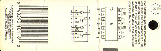
The 74HCT125

Here is the diagram for the CMOS chip, scanned in from the packaging. Since this is a tri-state chip, and lights are only two states (on or off), the third state had to be disabled by attaching all the OE pins to ground. The 5VDC from an AC adapter comes in through the VCC pin, three pins from the parallel port are attached to 1A, 2A, and 3A, and the three relays are attached accordingly to 1Y, 2Y, and 3Y.
The Port

A diagram of a parallel port. Pins 2, 3, and 4 are the data pins that are controlled with inpout32.dll. Image courtesy of
The Code Project.
The Light

Here is the traffic light. This thing is huge.
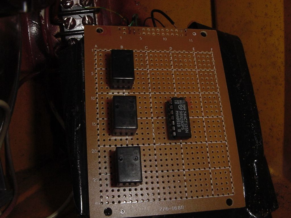
The PC Board (top)

Here is the layout for the top of the PC board. The three relays are on the left, and the CMOS chip in its holder on the right. I probably could have chosen a smaller PC board.
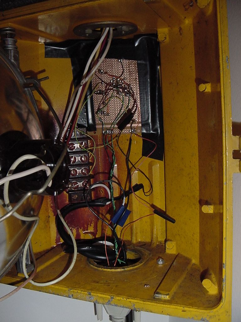
The Inside

A view inside the light, behind the green bulb. Not the prettiest thing, but it works!
The PC Board (bottom)

A close-up of my hideous soldering job. The green-blue wires coming from the bottom are the three pins on the parallel cable. Every orange wire carries 5VDC from the AC adapter. Every black wires is connected to ground. The black-brown and yellow-green wires that go off to the left of the picture carry 125VAC to the three lights.
The Bottom

A view from below the light. Holes were drilled in the wood to mount the switch and D-Sub connectors. The two black wires behind the parallel cable are for power.
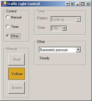
The UI
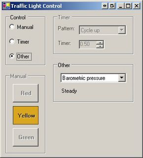
The user interface for controlling the light. The lights can be controlled manually, can be controlled to do different patterns based on a timer, or can download information (in this case the barometric pressure for my town) and display it. I also used the same code so that people can control the lights over IRC and AIM.
The Software
The program that runs the traffic light is written in C# and is based around the inpout32.dll that can be
found here. Unfortunately I cannot host my entire project, since I have no webspace with which to do so, so here are the important pieces of code from the project (or you can look at the project on The Code Project page).
[DllImport("inpout32.dll", EntryPoint="Out32")]
public static extern void Output(int adress, int value);

private const int LPT_PORT = 0x378; // 888
private const int RED = 0;
private const int YELLOW = 1;
private const int GREEN = 2;

bool[] light = new bool[3];

private void UpdateLights() {
 int data = 0;

  for (int i = 0; i <= 2; i++)
    if (light[i])
      data += (int)Math.Pow(2, i);

  Output(LPT_PORT, data);
}
The first statement is a declaration for importing the external Output() function. inpout32.dll should in the same directory as the application.
The value for LPT_PORT is unlikely to be anything different than 0x378; however, the value for your computer can be found in the properties page of the LPT port in Device Manager. Under the Resources tab, the first value in "I/O Range" should be the your LPT_PORT constant. In my case, I/O range reads "0378-037F", so I just use 378.
The next three constants are just arbitrary value I chose for the lights. To enable or disable certain lights, I just change the values in the boolean array light[] and then call UpdateLights().
For example, if I wanted to light only the green light, I'd do the following:
light[GREEN] = true;
light[YELLOW] = false;
light[RED] = false;
UpdateLights();
Simple as that.